
Physics
Cambridge IGCSE
Cambridge IGCSE
TOPIC 4A: ELECTRICITY
At the beginning of section 4.2b, we met the idea of resistance. The more components there are in a series circuit, the harder it is for current to flow. There is more resistance in the circuit. Some small components (like L.E.D.s which we will meet later) only need a small current. A large current might destroy the component. For this reason we need a 'resistor' in the circuit - a small component that controls the current.
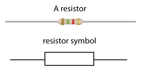
Figure 1. Resistors
The basic rule for resistors is common sense - the higher the resistance, the less current flows. It resists the flow of current around a circuit. The best way to understand the behaviour of resistors is to carry out a simple investigation, measuring voltage and current:
Required Practical: Describe an experiment to determine resistance using a voltmeter and an ammeter
We can investigate resistance by measuring the current flow for different voltages. To change the voltage, it is easier to use a variable power supply instead of changing the cell or battery each time. (See figure 2). We use an ammeter and voltmeter as described in section 2.2. Here is the circuit needed:

Figure 2. Investigating the properties of a resistor
As the voltage increases, it forces more current through the resistor, but the size of the current stills depends on the resistor as shown below:
The table shown here gives some typical (but simplified) results:
| Voltage (Volts) | Current (Amps) |
|---|---|
| 0 | 0 |
| 4 | 1 |
| 8 | 2 |
| 12 | 3 |
Table 1. Typical results for a resistor investigation
Conclusion
As can be seen in the investigation above, the higher the voltage, the higher the current. See the next section to find out how to process the results and calculate the resistance in this circuit.
Note: It is possible to do this investigation using a variable resistor to change the p.d. across a fixed resistor that is under investigation. You will learn more about variable resistors in this section.
The current in the practical example above is always 4 times smaller than the voltage. We say that this is a '4' resistor - reducing the current by a factor of 4 compared to the voltage. However we need a unit.
The unit of resistance is called the ohm (named after the famous electricity scientist George Ohm), and given the symbol Ω (the Greek letter omega).
The resistor above is a 4Ω resistor from the results table.
To calculate resistance:
| resistance = | voltage |
| current |
| R = | V |
| I |
[ohms] = [volts] / [amps]
This famous formula is called 'Ohm's Law' and is true for resistors, wires, and many other components.
Note that current is given the letter 'I', not 'C', for historical reasons.
If we plot the results from table 1 on a graph, we get a straight line through the origin. (A tell-tale sign that the component follows Ohm's Law). This straight line also shows us that the current is proportional to the voltage.

Figure 3. Current - resistance graph for a resistor
Note: In some books and web pages, the axis are reversed, but the Ohm's Law graph is still a straight line.
Here are a few practice questions to gain confidence with the Ohm's Law formula:
Example:
A 4 Ω resistor is connected to a cell, and has 1.7 amps flowing through it. What is the voltage of the cell?
Answer:
We know that
R= V/I and so V = I x R, and 1.7 amps is the current. R = 4 Ω.
Therefore voltage = 1.7 x 4 = 6.8 volts
Questions:
1. A 20 Ω resistor is connected to a 6 V battery. What current flows through it?
We know that R= V/I, So :
| I = | V |
| R |
| I = | 6 |
| 20 |
2. A 4 kΩ resistor has a current of 2 mA flowing through it. What is the p.d. across the resistor?
This is a little harder as we first need to convert units:
As 1 kΩ = 1000 Ω, then 4 kΩ = 4000 Ω
There are 1000 mA in an amp. So 2 mA = 0.002 A ( 2 ÷ 1000)
p.d. means potential difference - the voltage across the component.
Therefore as R=V/I, then V = I x R;
V= 0.002 x 4000
V
= 8 V
3. Two identical resistors R are connected to a 6 V cell as shown.

The current flowing from the cell is 4 A. What is the value of the resistor R?
In a parallel circuit, the current splits, and here both branches of the circuit are identical. Therefore 2 amps flows down each branch.
Also for a parallel circuit, the voltage across all branches is the same as the cell, so each resistor has a p.d. of 6V.
| R = | V |
| I |
| R = | 6 |
| 2 |
If we connect two resistors in series, it makes it harder for current to flow - the total resistance has increased. In fact, we can just add the value of the resistors together to find the total resistance.
Rtotal = R1 + R2 + .....
If we connect two resistors in parallel, there are now two paths for the current, and it makes it easier for current to flow round the circuit. The total resistance is lower and the current is higher.
These rules are compared here in some simple circuit examples:

Figure 4. Resistors in series and parallel
To calculate the resistance in parallel needs a new formula, and here it is given for just 2 resistors:
| 1 | = | 1 | + | 1 |
| Rtotal | R1 | R2 |
Example:
Calculate the total resistance when a 6
Ω resistor and a 2 Ω resistor are connected in parallel.
| 1 | = | 1 | + | 1 |
| Rtotal | R1 | R2 |
| 1 | = | 1 | + | 1 |
| Rtotal | 6 | 2 |
| 1 | = | 4 |
| Rtotal | 6 |
However this is not the final answer! remember to 'flip' the fraction upside down to find Rtotal !!
Rtotal = 6/4 = 1.5 Ω
Questions:
4. Calculate the total resistance when two 8
Ω resistors are connected in parallel.
| 1 | = | 1 | + | 1 |
| Rtotal | R1 | R2 |
| 1 | = | 1 | + | 1 |
| Rtotal | 8 | 8 |
| 1 | = | 2 |
| Rtotal | 8 |
and therefore Rtotal = 8/2 = 4 Ω
Note: When any 2 identical resistors are connected in parallel, the resistance halves. If in series, it doubles!
Notice that in the middle diagram in figure 4, joining resistors end to end makes a higher total resistance. Similarly, if we connect two identical wires together end to end, we can add together the resistances of each section. A long wire can be considered to be several short sections joined together. Therefore, the longer the wire, the higher the resistance. In fact, the resistance is directly proportional to the length. If you double the length, the resistance will be doubled.
What about the diameter of a wire? Well in this case - just like a water pipe - a thin wire makes it more difficult for a current to flow. It is actually the cross-sectional area that determines the resistance, with a smaller cross-sectional area leading to more resistance. In fact the resistance is inversely proportional to the cross-sectional area. if you double the area, the resistance is halved.
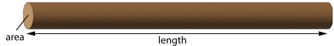
R ∝ length and R ∝ 1/(area)
Figure 5. The resistance of a wire
Harder Question:
5. A wire of length 2 m and cross-sectional area 1 mm2 has a resistance of 10 Ω. Calculate the resistance of a similar wire made of the same material, but with a length of 6 m and cross-sectional area 4 mm2 ?
We know that the resistance is proportional to the length, which is 3 times larger, so the resistance will be x 3, = 30 Ω.
However the area has also changed, to 4 times larger. Resistance ∝ 1/(area), so the resistance is ¼ of this.
so R = ¼ x 30 = 7.5 Ω
A variable resistor - as the name suggests - is just a device for varying the resistance, and this allows the current or p.d to change, or both, depending on the circuit constructed. A variable resistor symbol is just a rectangle with an arrow through, as shown in figure 6 below. This simple circuit shows a variable resistor used to alter the current flowing through a lamp, making it brighter or dimmer.

Figure 6. A variable resistor used to change the brightness of a lamp
When two resistors are connected in series to a cell, they have to share the cell voltage (the e.m.f.). So if 2 identical resistors are connected to a 6V cell, the resistors have a p.d. of 3V each across each one. When a voltage is divided between components in this way, it is called a potential divider circuit.
What happens if the resistors are not identical? How is the voltage split?
Ratio Method:
The voltage in a potential divider circuit is always split in ratio. Take the example shown here in figure 7:

Figure 7. Potential divider circuit
Here, the 6 V e.m.f. of the cell is split between the 10 Ω and 30 Ω resistors in a 1:3 ratio. The 10 Ω resistor will have a p.d. of ¼ of the e.m.f. (= 1.5 V) and the 30 Ω resistor will have ¾ of the e.m.f. (=4.5 V). The formula to do this calculation is here:
| R1 | = | V1 |
| R2 | V2 |
Alternative Method:
Another (longer) way to work this out is to calculate the current:
We know R = V/I, so that I = V/R, and the total resistance is just 40
Ω (adding the 2 resistors together).
So I = 6/40 =
0.15 A.
We can then use this current to find the p.d. across each of the resistors using V = I x R:
For the 10 Ω resistor, V = 0.15 x 10 = 1.5 V
For the 30 Ω resistor, V = 0.15 x 30 = 4.5 V
This method gives the same answers, but engineers can quickly work out the p.d. using a ratio method if they are confident with their maths!
Example:
Two resistors are connected in series to make a potential divider as shown here:
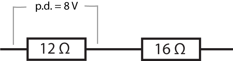
What is the potential difference across the 16 Ω resistor?
Answer:
First of all write down the formula for the ratio between resistance and voltage/p.d.:
| R1 | = | V1 |
| R2 | V2 |
| 12 | = | 8 |
| 16 | V2 |
A variable resistor can be made with three connections as shown below in figure 8. When used in this way, we call it a 'potentiometer' (or 'rheostat'):
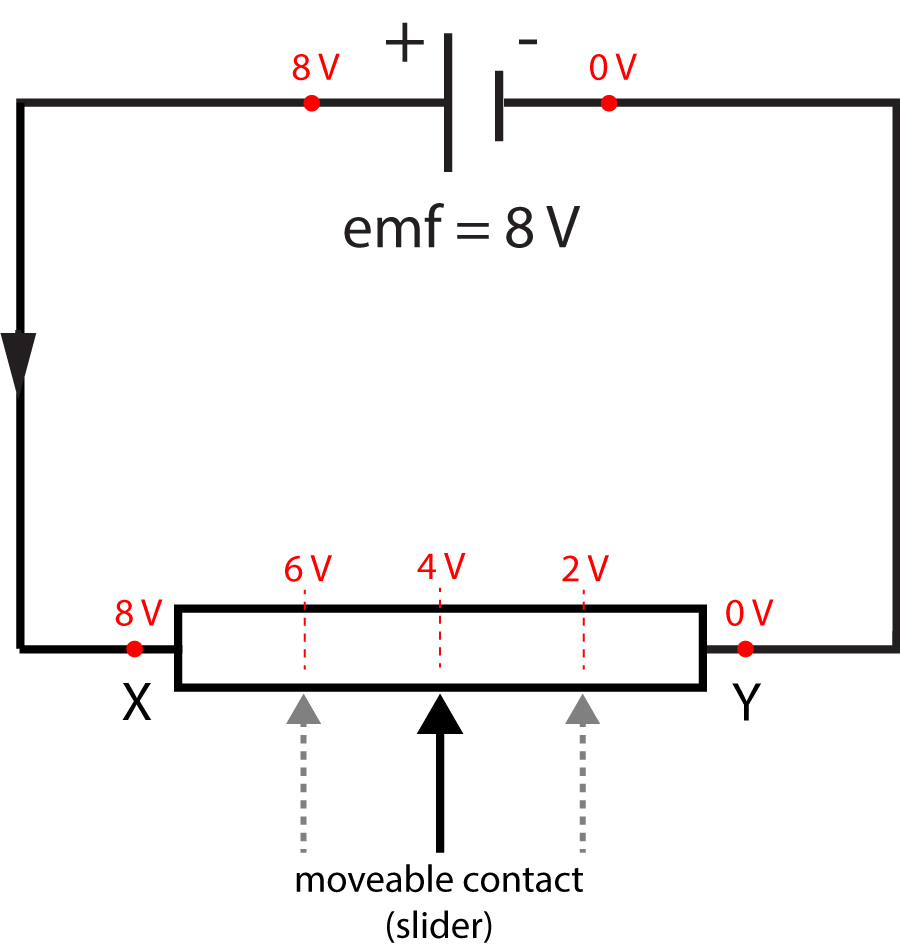
Figure 8. A variable resistor with three connections
The middle arrow is an electrical contact that can be moved to the left or right of the variable resistor. When the contact is in the centre, there are equal resistances on each side. If point X is considered to be at 8V potential, and point Y at zero potential, then the centre point will therefore be at 4V potential - the two equal halves of the resistor split the e.m.f. of the cell in two.
Moving the 'slider' to the left increases the potential as shown, and to the right would decrease the potential. Moving the slider therefore varies the p.d. across any component connected to it.
For example, the middle contact could be connected to a lamp and the variable resistor used to vary the brightness from fully 'on' to off, as shown in this YouTube video:
YouTube - How to use a variable resistor as a potential divider
Question:
6. The circuit shown here can be used to change the brightness of a lamp.
a) The circuit shown in figure 8 is used, with a lamp added to the sliding contact. The other end of the lamp must be connected to the negative end of the power supply/cell to allow current to flow back to the cell. (see below)
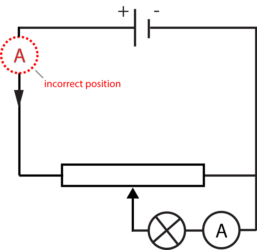
b) The ammeter must be added in series to the bulb. Note the incorrect position shown above - if in that location, it would measure the current through the lamp AND the variable resistor.
c) The brightness of the bulb (and current) in this circuit can be varied from maximum to zero. If the original circuit shown is used, the current can be varied from maximum to a lower value as the resistance increases, but NOT down to very small values and eventually zero. For this, the variable potential divider circuit shown here is required.
Now Try this quick 10 minute quiz on resistance: