

TOPIC 2: ELECTRICITY
At the beginning of section 2.2, we met the idea of resistance. The more components there are in a series circuit, the harder it is for current to flow. There is more resistance in the circuit. Some small components (like L.E.D.s which we will meet later) only need a small current. A large current might destroy the component. For this reason we need a 'resistor' in the circuit - a small component that controls the current.
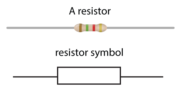
Figure 1. Resistors
The basic rule for resistors is common sense - the higher the resistance, the less current flows. It resists the flow of current around a circuit.
We can investigate resistance by measuring the current flow for different voltages. To change the voltage, it is easier to use a variable power supply instead of changing the cell or battery each time. (See figure 2). We use an ammeter and voltmeter as described in section 2.2. Here is the circuit needed:
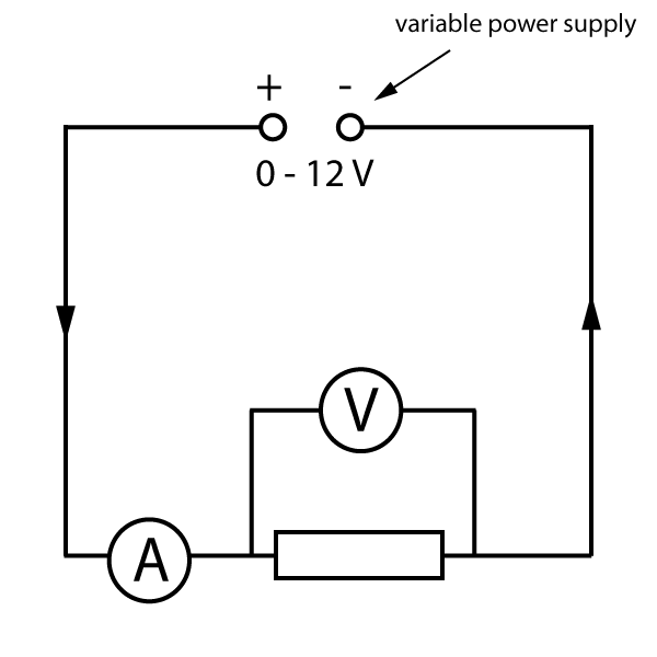
Figure 2. Investigating the properties of a resistor
As the voltage increases, it forces more current through the resistor, but the size of the current stills depends on the resistor as shown below:
The table shown here gives some typical (but simplified) results:
| Voltage (Volts) | Current (Amps) |
|---|---|
| 0 | 0 |
| 4 | 1 |
| 8 | 2 |
| 12 | 3 |
Table 1. Typical results for a resistor investigation
As can be seen here, the higher the voltage, the higher the current. The current in this example is always 4 times smaller than the voltage. We say that this is a '4' resistor - reducing the current by a factor of 4 compared to the voltage. However we need a unit.
The unit of resistance is called the ohm (named after the famous electricity scientist George Ohm), and given the symbol Ω (the Greek letter omega).
The resistor described by the results table above is a 4Ω resistor.
To calculate resistance:
| resistance = | voltage |
| current |
We can rearrange this to give the following:
voltage = current x resistance
V = I R
[volts] = [amps] x [ohms]
This famous formula is called 'Ohm's Law' and is true for resistors, wires, and many other components.
Note that current is given the letter 'I', not 'C', for historical reasons.
If we plot the results from table 1 on a graph, we get a straight line through the origin as shown below. (A tell-tale sign that the component follows Ohm's Law). This straight line also shows us that the current is proportional to the voltage, and the component is therefore called an 'ohmic conductor'.
Note that If you reverse the direction of the applied voltage, the current also reverses, giving the negative values shown here:
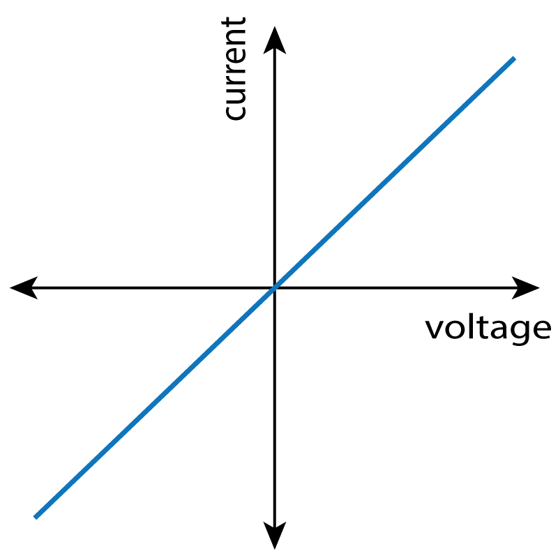
Figure 3. Current - resistance graph for a resistor
Note: In some books and web pages, the axis are reversed, but the Ohm's Law graph is still a straight line.
Here are a few practice questions to gain confidence with the Ohm's Law formula:
Example:
A 4 Ω resistor is connected to a cell, and has 1.7 amps flowing through it. What is the voltage of the cell?
Answer:
We know that voltage = current x resistance, and 1.7 amps is the current. R = 4 Ω.
Therefore voltage = 1.7 x 4 = 6.8 volts
Questions:
1. A 20 Ω resistor is connected to a 6 V battery. What current flows through it?
We know that V= I x R, So :
| I = | V |
| R |
| I = | 6 |
| 20 |
2. A 4 kΩ resistor has a current of 2 mA flowing through it. What is the p.d. across the resistor?
This is a little harder as we first need to convert units:
As 1 kΩ = 1000 Ω, then 4 kΩ = 4000 Ω
There are 1000 mA in an amp. So 2 mA = 0.002 A ( 2 ÷ 1000)
p.d. means potential difference - the voltage across the component.
Therefore as V = I x R;
V= 0.002 x 4000
V
= 8 V
3. Two identical resistors R are connected to a 6 V cell as shown.
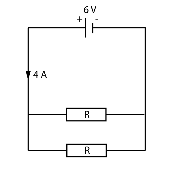
The current flowing from the cell is 4 A. What is the value of the resistor R?
In a parallel circuit, the current splits, and here both branches of the circuit are identical. Therefore 2 amps flows down each branch.
Also for a parallel circuit, the voltage across all branches is the same as the cell, so each resistor has a p.d. of 6V.
| R = | V |
| I |
| R = | 6 |
| 2 |
If we connect two resistors in parallel, there are now two paths for the current, and it makes it easier for current to flow round the circuit. The total resistance is lower and the current is higher.
These rules are compared here in some simple circuit examples:
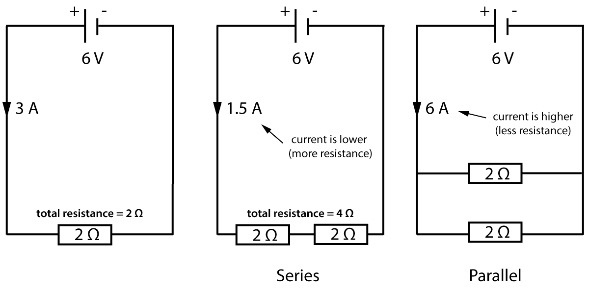
Figure 4. Resistors in series and parallel
Note that in the middle diagram, the total resistance is simply 4Ω. It is the sum of the two resistors. This is the total, also called the equivalent resistance. This means "the value of a single resistor that would have the same value as the combined resistors".
We can write this as:
Rtotal = R1 + R2
This is a very simple formula!
You will not be asked to calculate the resistance of 2 resistors in parallel, as this is a bit more complicated.
Notice that in the middle diagram in figure 4, joining resistors end to end makes a higher total resistance. Similarly, if we connect two identical wires together end to end, we can add together the resistances of each section. A long wire can be considered to be several short sections joined together. Therefore, the longer the wire, the higher the resistance.
What about the diameter of a wire? Well in this case - just like a water pipe - a thin wire makes it more difficult for a current to flow. The thinner the wire, the higher the resistance.
Investigate the factors affecting the resistance of electrical circuits.
In this practical, you need to be able to follow a circuit diagram and set up the circuit needed to complete the following investigations:
The circuit diagram for the wire investigation should look something like this:
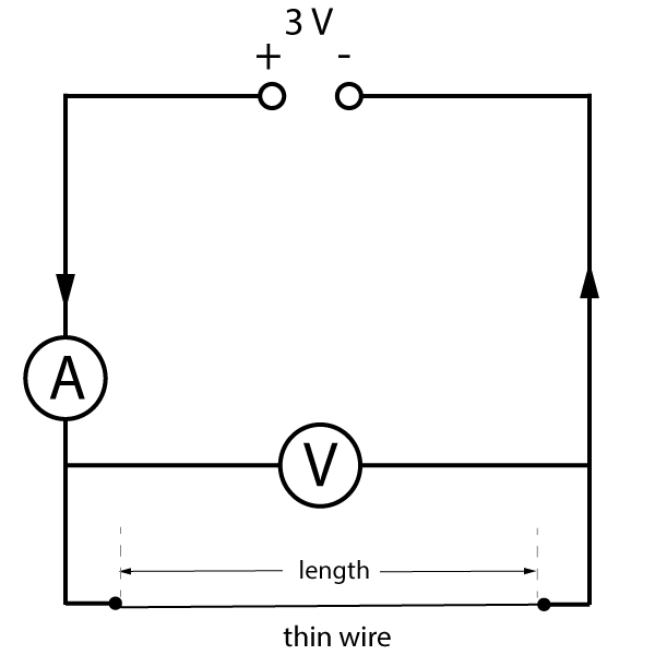
Figure 5. How does the length of a wire affect resistance?
The potential difference across the wire and the current through it can be measured for a range of lengths. The resistance of the wire can then be calculated using the current and voltage readings.
Notes:
The wire in this experiment could be replaced with a network of resistors to investigate how connecting them in series or parallel affects the total resistance of the circuit.
Now test your understanding using these quick, 10 minute questions on this topic from Grade Gorilla: