

TOPIC 2: ELECTRICITY
The video below shows a tap with water flowing out. We all know that turning a tap on and off will change the flow of water. The water pressure in the pipes makes water flow out, and the tap controls this pressure.
This is very similar to a simple circuit:
Youtube - How circuits work.
The tap is like our power source in a circuit - the cell.
The water flowing out is like the electrical current flowing round a circuit.
This analogy helps us to understand the difference between current and voltage in circuits.
A higher pressure - or 'kick' - from the tap will produce more current. The pressure or kick from the cell in a circuit is called the voltage (V), and is measured in volts (V). The current (I) flowing in the circuit is measured in amps (A).
The video shows that the current also depends on the resistance in the circuit, not just on the voltage. We will learn more about resistance in the next section, 2.3. The higher the resistance, the lower the current flowing in the circuit.
If you can remember this way of thinking about electricity, you will have a better grasp of the next few sections.
To measure current we need an ammeter (spelt like 'ampmeter but without the 'p'). The symbol for an ammeter is shown below - just a letter 'A' with a circle around it.
An ammeter is always placed in series with the component being measured as shown in figure 1. An amp is a large unit, so milliamps (mA) are often used.
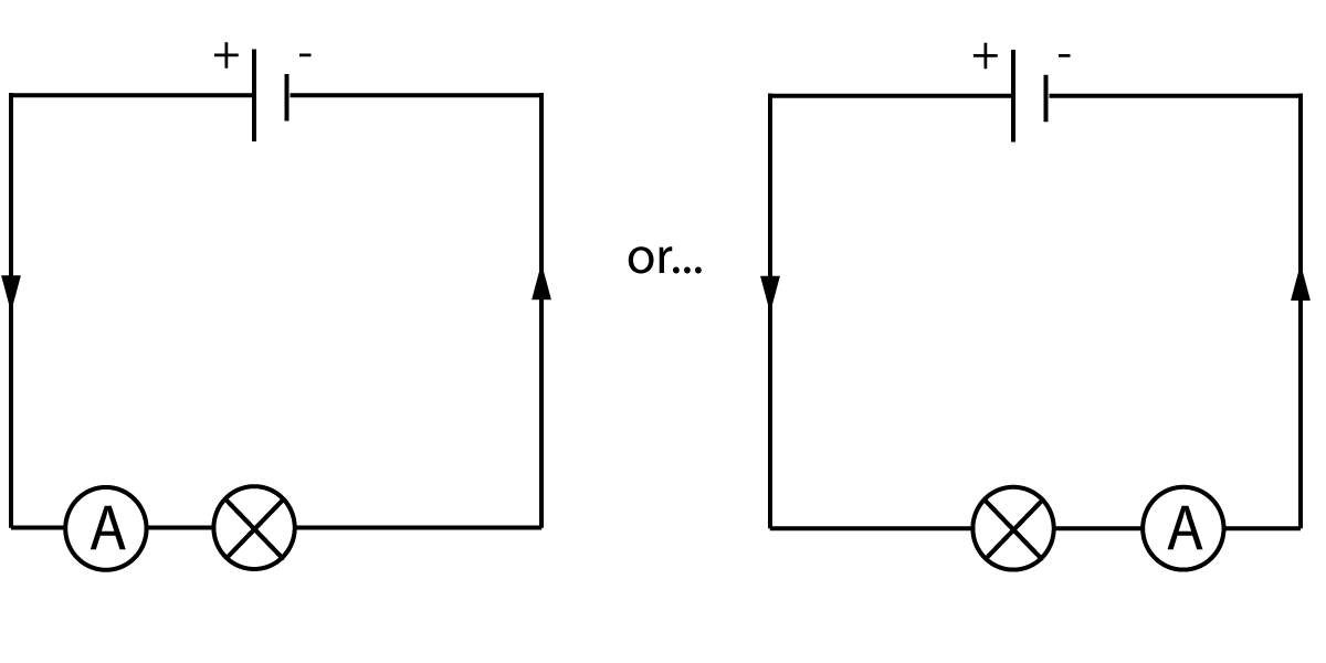
Figure 1. Using an ammeter.
Note that the ammeter can be placed before or after the component, as the current flowing in to it will be the same as the current flowing out.
To measure voltage, we use a voltmeter as shown below. The voltmeter is always connected in parallel with the component being measured.
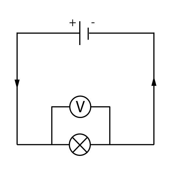
Figure 2. Using a voltmeter.
The voltage across any component is called the potential difference, or p.d. for short.
Note that ammeters and voltmeters are designed to measure electrical quantities without interfering with the circuit. For example, adding an ammeter in series will not affect the current flowing at all -it has effectively no resistance. (see section 2.3 for more on resistance).
The current flowing through a bulb is never used up, the same current flows in to it as flows out the other end. This is just like the water going in to one end of a pipe - it will match the volume of water coming out the other end. Have a look at the circuits shown here in figure 3, and see if you can figure out what is happening:
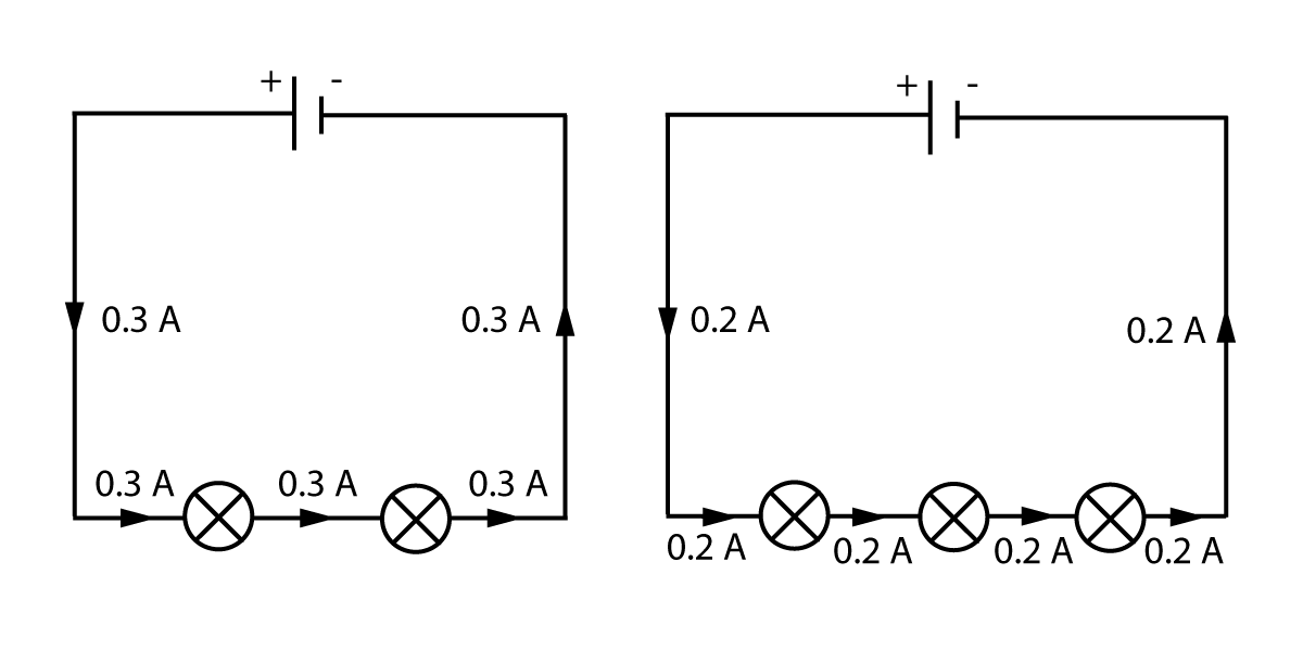
Figure 3. Current in a series circuit.
As we can see from the diagrams above, if we put more and more bulbs in a series circuit, the current decreases (because the total resistance increases). However there is one rule that is always true:
It does not matter where in the series loop we measure the current, as it just goes round and round, it will be the same at all points.
if we put components in parallel, it makes a split in the circuit, with 2 or more ways for the current to flow. This means - just like water in pipes - that some will go one way, and some current the other way.
However the total current flowing will always be the same.
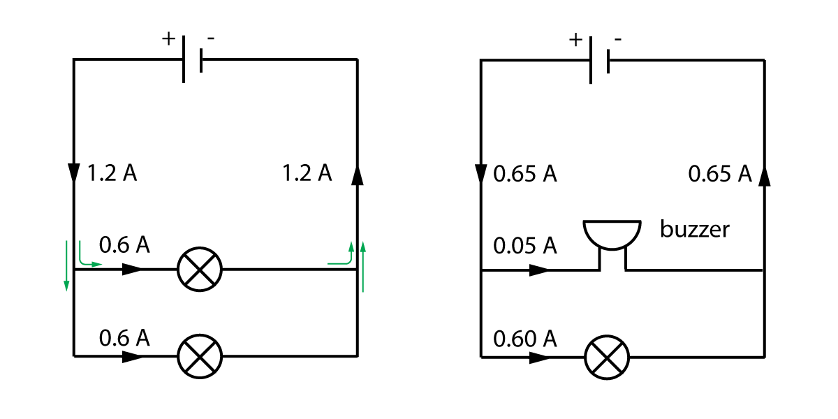
Figure 4. Current in a parallel circuit.
Notice that in the first diagram, both branches get the same current, because both branches have the same bulbs in.
However in the second circuit, there is a buzzer in one branch which does not need much current to operate. The current in each branch is different, but they still add up to the total current of 0.65 A. The rule above is still true.
Have a go at these questions to check you understand current in circuits:
Questions:
1. Two bulbs, X and Y are connected in series to a 6V cell.
a) The diagram should look something like this, with all the components in one loop:
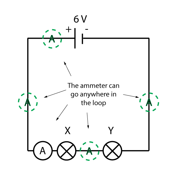
Notice that the ammeter can be anywhere in the loop, as the current around a series circuit is the same at all points.
b).
(i) 1 amp = 1000 mA, so 500 mA = 0.5 A
(ii) As the current is the same at all points, bulb X must also get 0.5 A current.
2. What is the current shown on the ammeters labelled P and Q in the circuit shown here?
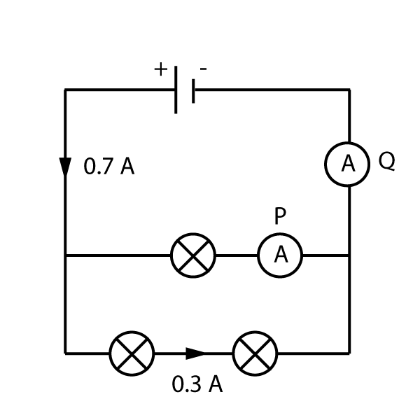
The cell produces a total current of 0.7 A. If 0.3 amps flows along the bottom branch, then the remainder 0.4 amps flows through the top branch.
Ammeter P shows 0.4 amps.
Once the current recombines and flows back to the cell, it equals 0.7 amps again.
The current through ammeter Q is 0.7 amps.
Voltage in circuits is not quite as easy to understand, but basically it works in reverse to the rules for current.
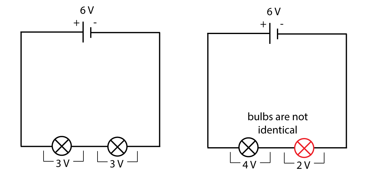
Figure 5. Voltage in series circuits
As you can see from figure 5, the cell produces a voltage of 6 V, but in the first diagram each bulb only has a p.d. of 3 V. As each bulb is identical, they share 3 V each. However if the components are different, the split may not be identical. For example one bulb may have 4 V across it, and another may have 2 V p.d. as shown in the second diagram.
From the diagrams above, we can say that:
When components are connected in parallel as shown in figure 6, all of the branches have their own connections to the cell. This means that they all get the entire 'kick' from the cell - all of the components have the same voltage as the cell.
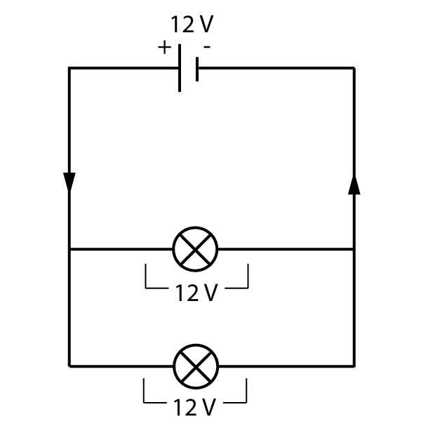
Figure 6. Voltage in parallel circuits
So in parallel circuits:
Here is a summary of all of the above points:
1. Current in series - the same
2. Current in parallel - splits
3. Voltage in series - splits
4. Voltage in parallel - the same
Have a go at the questions here to check you understand this - try not to look at the solutions until you have got your own answers:
Questions:
3. A buzzer is connected to a cell. Draw a circuit diagram to show how the current through the buzzer and the potential difference across it can be measured.
a) The diagram should look like this:
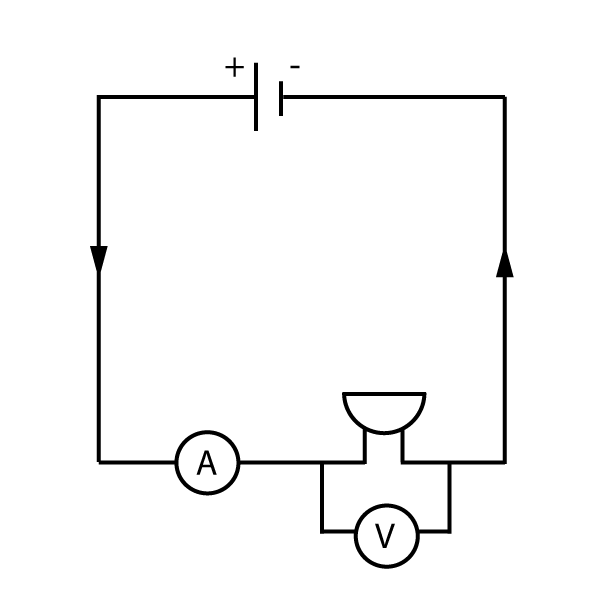
Note that the cell, buzzer and ammeter are all in series (in a single loop), and the voltmeter is in parallel with the buzzer only.
4. All the bulbs in this circuit are identical. What are the readings on the ammeter and voltmeter in this diagram?
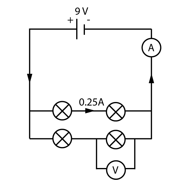
This is a tough question combining many aspects of this section:
Current reading:
The bulbs are all identical. That means the current in both branches of the parallel circuit must be the same - 0.25 A in each. Therefore the total current flowing out of the cell and back in to it must be 0.50 A. (green box rule 2).
Voltage reading:
The bottom branch is in parallel with the top branch of the circuit. According to rule 4 in the green box, the voltages must be the same as the cell, 9V for each branch.
The voltage in a series circuit is split between the two components. (Rule 3). As the two bulbs are identical, each gets 4.5 volts, or a p.d. of 4.5 V.
Now test your understanding using these quick, 10 minute questions on this topic from Grade Gorilla:
If you find this topic tough, there is also a really basic revision quiz on circuits here: