TOPIC 2: ELECTRICITY
We rely on electricity in our everyday lives and often overlook its significance, yet it wasn't long ago that we had little understanding of it. The electric light bulb was invented in 1802, but it wasn't until the early 20th century that it became a standard feature in households.
Electricity has had a huge transforming effect on society, from power for kettles at the flick of a switch, to our mobile phone network and internet that we use constantly.
In this topic, we will be learning how electricity provides power and how to control it in circuits.
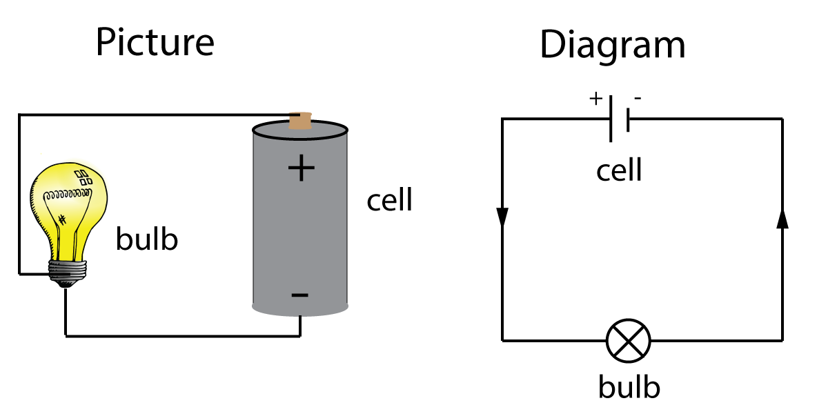
Have you ever used a battery or cell to light up a bulb? It is a simple circuit as shown here. on the left is a picture of what it looks like in real life, and on the right is a simplified diagram:

Figure 1. A simple circuit diagram.
There are a few things to notice here in the circuit diagram - the wires connecting the cell and a bulb are all at 900, making a rectangular shape. This is to make the diagram easier to understand, especially when there are many wires involved.
Also there are arrows showing which direction electricity is moving around the circuit. We always draw the electric current flowing from the positive to the negative end of the cell, around the circuit as it shows here.
There are some standard circuit symbols that you need to be familiar with at the beginning of this topic, as shown here:
| 1. | A simple cell |  |
This is simply drawn as a long line and a short line, the long line indicating the positive (+) end of the cell. |
| 2 | A battery |   |
A battery is a line of cells joined together end to end. There are two ways of drawing this as shown here. The second version just uses a dotted line instead of drawing all of the individual cells. |
| 3. | A bulb or filament lamp |  |
These - like LEDs that you will meet later -light up when an electric current passes through them. They are useful to indicate that a current is flowing. |
| 4. | An on/off switch |  |
A simple switch that stays on or off, like a light switch. |
| 5. | A push switch |  |
A switch that only works when you hold it down, like a door bell. |
When we start making circuits with several parts - or electrical components as they are called -the diagrams can be arranged in two basic ways. The circuits shown in figure 2 show two bulbs and a single cell arranged side by side (a series circuit) and in two parallel branches ( hence called a parallel circuit).

Figure 2. Series and Parallel circuits
You will learn more about these circuits in section 2.2, but you need to be able to recognise them and describe their basic functions.
Try these questions to see if you follow how these circuits work. You should try building series and parallel circuits yourself at school to gain experience in this topic.
Questions:
1. In a school or office, there are many light bulbs in use in a single room. How should these be arranged?
The answer is (a) in parallel. This is because if one bulb fails, the others will stay on. It also means you can spot which bulb is broken. If they are wired in series, then if one breaks, they ALL turn off and then you cannot find the broken one easily!
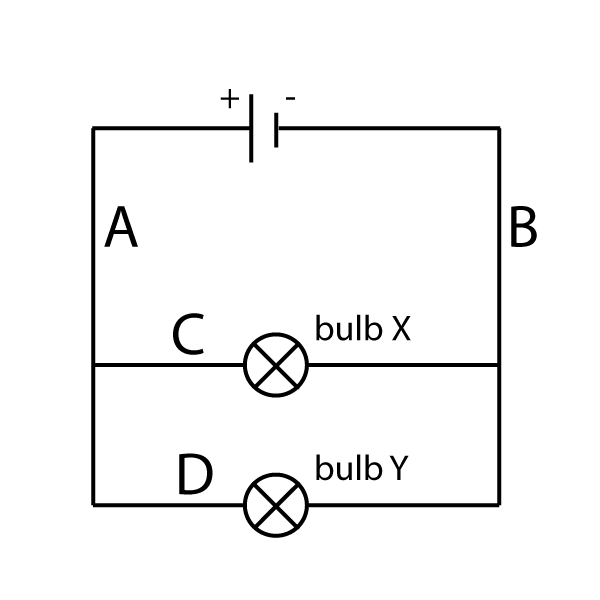
2. A circuit is made using two bulbs, X and Y, arranged in parallel as shown here.
In which position - A, B, C or D - should a switch be added to turn X on and off, but leave Y on?

The switch should go in position C. This is because you need to break the current flowing in the top branch, but leave current flowing in the bottom branch.
There are no additional questions for this section - move on to section 2.2 to learn about current and voltage.