Double Award
TOPIC 4A: ELECTRICITY
In section 4.2b, we covered some basic 'components' (parts of a circuit) including cells, switches and lamps/bulbs. In this section we will take a closer look at some other common components in circuits, and learn a bit more about how they function.
Here are a few other common components that you should be aware of, and be able to understand in a circuit diagram:-
| A power supply |  |
For example, a laboratory 12V power supply used instead of cells. Learn more about a.c. and d.c. power in section 4.4. |
| A heater (or heating element) |  |
As found in room heaters, hair dryers and toasters. |
| A motor |  |
As found in toy cars - uses electricity to turn the wheels. |
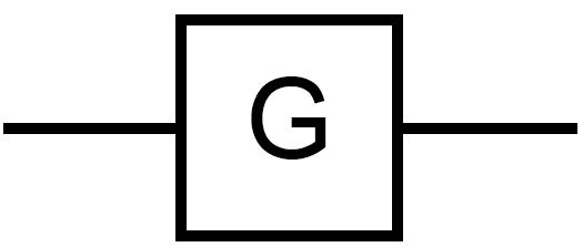
| A generator |  |
Generates electricity by spinning the generator, as found in wind turbines. |
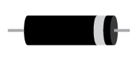
| A fuse |  |
See section 4.4 on electrical safety for how these are used. |
| Variable Resistor |
|
A resistor that can be increased or decreased, as found in light dimmer switches or old-style radio volume controls. |
Note: Additionally, you may come accross loudspeakers and buzzers in circuit diagrams , which are not included in the requirements for this course:
| A loudspeaker |  |
Produces sound waves from electrical signals. |
| A buzzer | A standard buzzer or more modern 'peizo-sounder'. |
Diodes are very clever components that work like one way gates. Current can only go through one way.
Light Emitting diodes (LEDs) are simply diodes that emit light when a current flows through it. Otherwise it behaves (almost) exactly like a normal diode. You can buy LEDs in many different colours, and as they are getting more and more efficient, they are becoming more common place and used widely for household and office lighting. They are also used in T.V. sets, traffic lights, power indicators and many more applications.
| Diode |  Current → |
 |
| LED (light emitting diode) |
 |
 |
Figure 2. Diodes and LEDs
Questions:
1. A small heater has two heating elements connected in series to a 24 V power supply. An ammeter is connected to measure the current through the heating elements.
Draw a circuit diagram to show these components in the correct places.

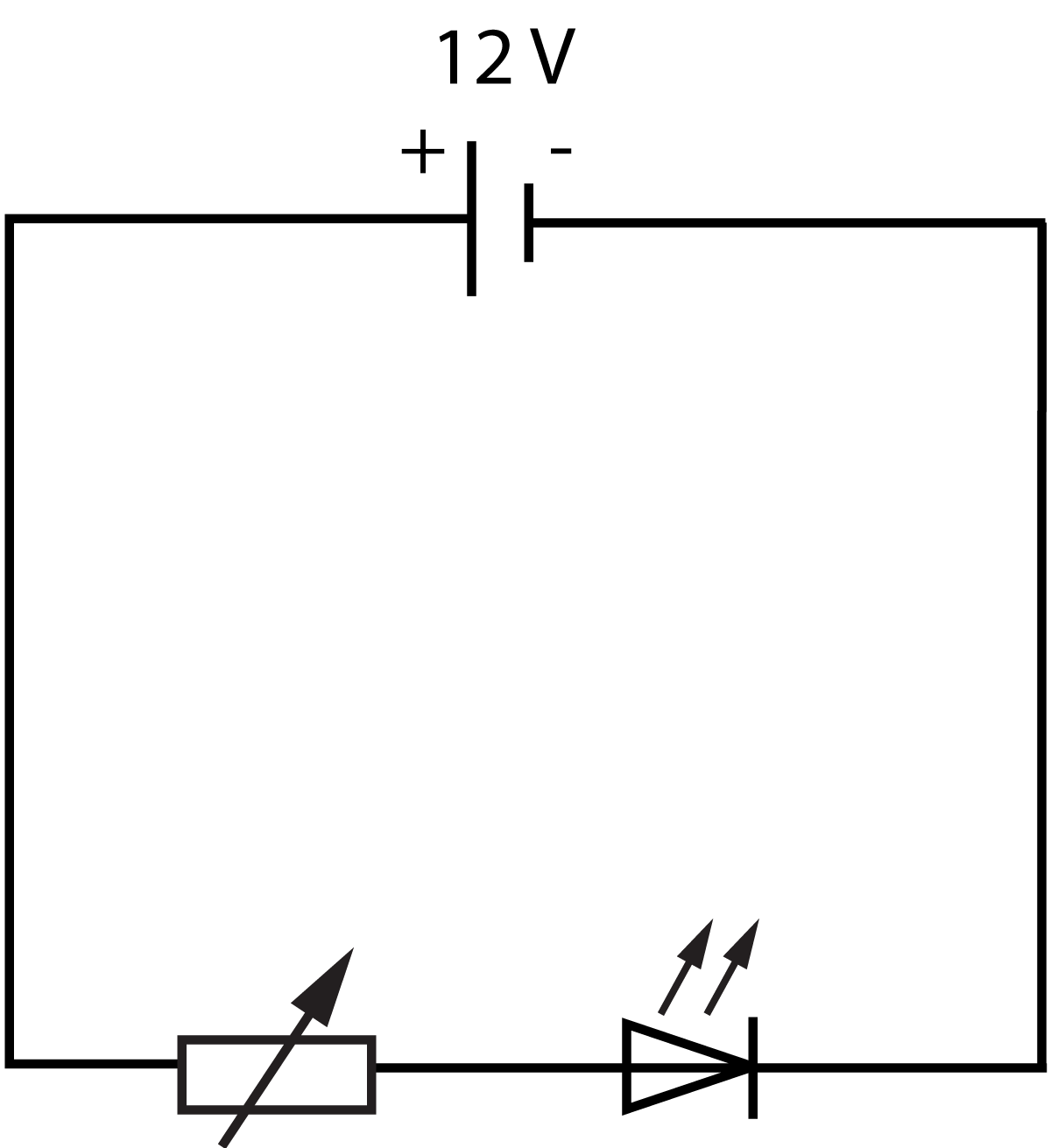
2. An LED is connected in series with a 12V cell and a variable resistor.
a) The circuit diagram should look like this. Note that the L.E.D. arrow must be in the direction of current flow from positive to negative.

b) A resistance of 1.2 kΩ is equal to 1200 Ω which is larger than 600 Ω.
Therefore the current will decrease, which will make the LED less bright/dimmer.